This is a description of how we at Johannas Stadsodlingar (urban farms) and Concinnity together have built Johanna’s aquaponic pilot facility. We want to share how we did it and our thinking behind it. There is quite a lot to think about, so there will be several posts to cover most things.
- Part 1 – start and prior knowledge
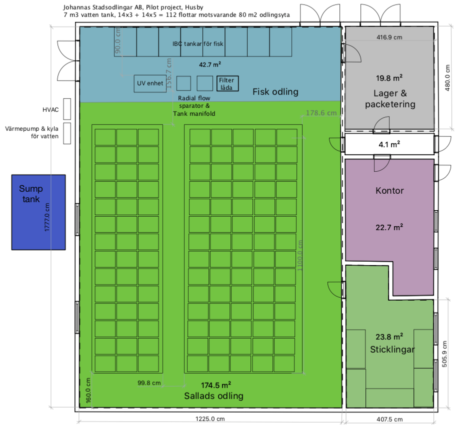
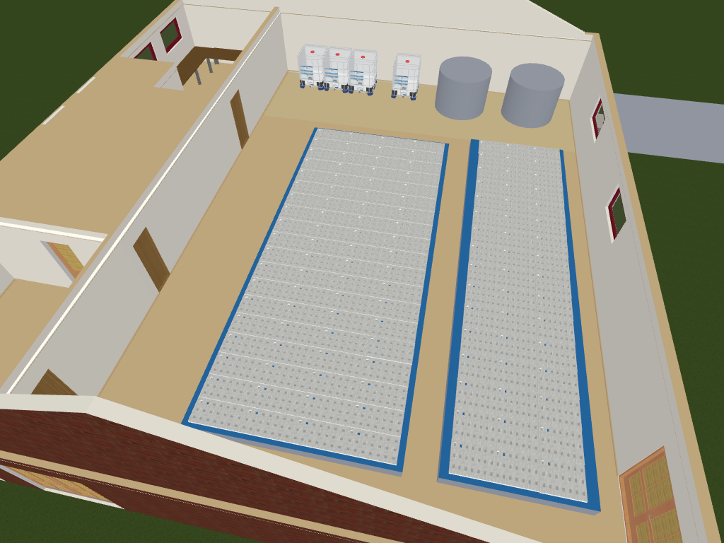
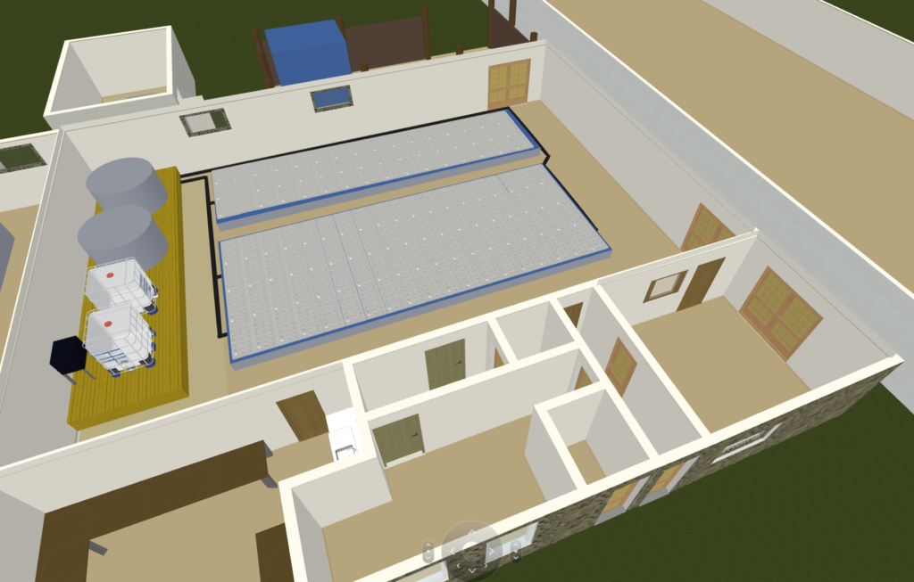
- Part 2 – design
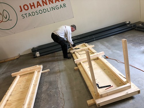
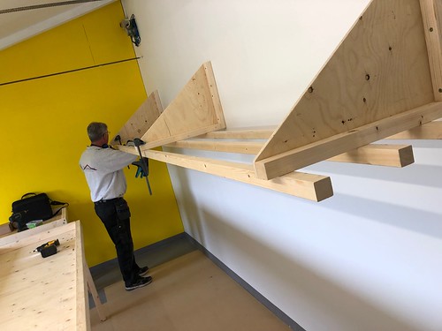
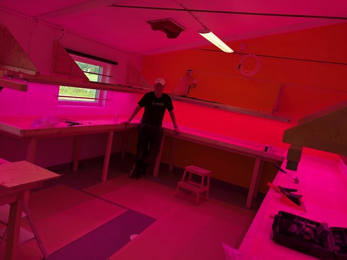
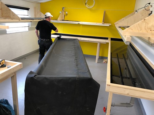
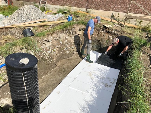
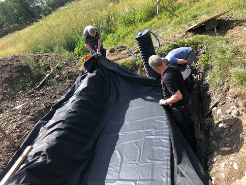
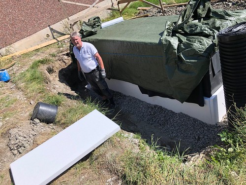
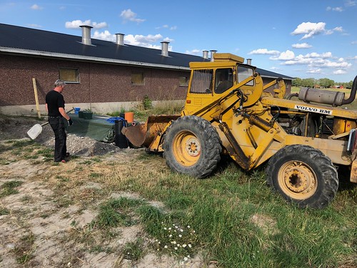
- Part 3 – build log
- Part 4 – water quality and nutrients testing
- Part 5 – production management
- Part 6 – distributed ledger/block chain integration (this post)
Cultivation Management Platform
The digital systems we have built are based around the vision we set out with at the start of the project. We call it the Cultivation Management Platform.
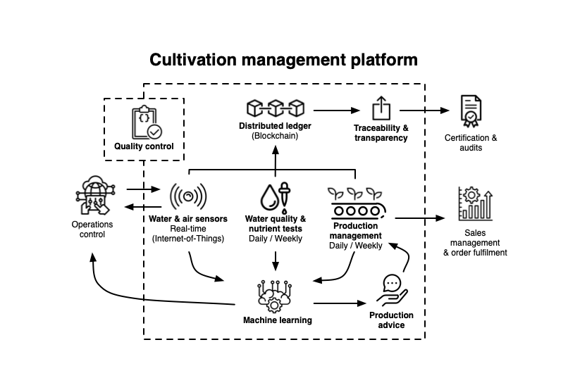
The CMP consists of four parts:
- Water quality and nutrients tests
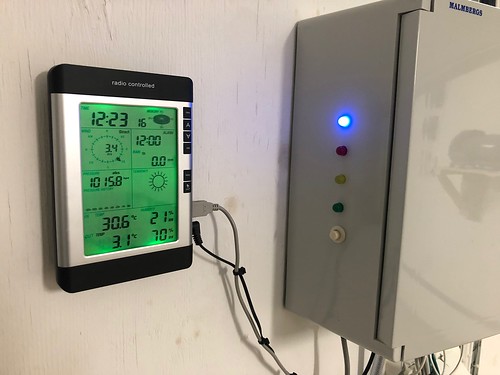
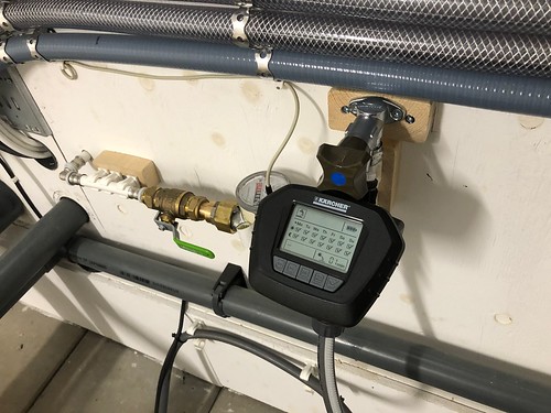
- Water, air and automation sensors
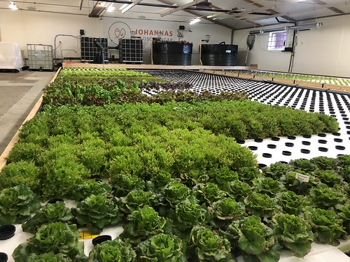
- Production management
- Distributed ledger / block chain
In this part we will describe our work around integrating a distributed ledger/block chain system.
We have built a system that demonstrates how to use a distributed ledger. A distributed ledger is a database that can be shared between many different parties, where all parties jointly control the information and where all data stored is ”permanent”, i.e. it can in principle not be changed after having been recorded. This may sound very impractical, but instead of changing data you create a reference to the original information and add a change. In this way, all changes to the database become visible to all parties. The blockchain is the underlying technology used to ensure that the information stored in the database cannot be changed afterwards. (This is of course a very simplified description of how a distributed ledger works in practice!)
We have gained access to IBM Food Trust (IFT) to build our blockchain demonstration in collaboration with IBM and Atea, a Swedish IBM partner. IFT is a distributed ledger based on the open-source software Hyperledger that implements a blockchain-based database. IFT provides APIs for storing data in and retrieving data from the blockchain.
System overview
Data from our production tracking system is transformed to ”fit” in IFT and sent there for storage (XML Gen). This is done using automation so that data in IFT is continuously synchronized with the production tracking system. A second part, Data display, retrieves information from IFT. We present a list of all harvests that have been made and you can choose a harvest to get a detailed description of all the steps that this particular plant went through on its way from seed to finished product.
Data
The data we store in IFT is based on the core of the data we generate in the production management system. This includes every step in the tracing of a plant from germination to harvest. All data stored in IFT gets unique IDs which we then use when we retrieve information from IFT in the client app (Data display). In this way, we have been able to build the client so that it does not depend on any part of the original information from the production tracking system, but all information comes from IFT.
Implementation
The system consists of two parts. The first part, XML Gen, retrieves data from the production tracking system and, after transforming this data into XML, sends to IFT for storage on the blockchain. The second part, Data display, retrieves data from IFT and presents it as web pages. This part fetches the information from IFT, where data is delivered in the JSON format, and after transforming this data, we create views as web pages. Note that the Data display is completely independent of the original information stored in the production management system. Data display part can be run as a completely independent service since it retrieves all necessary information from IFT.
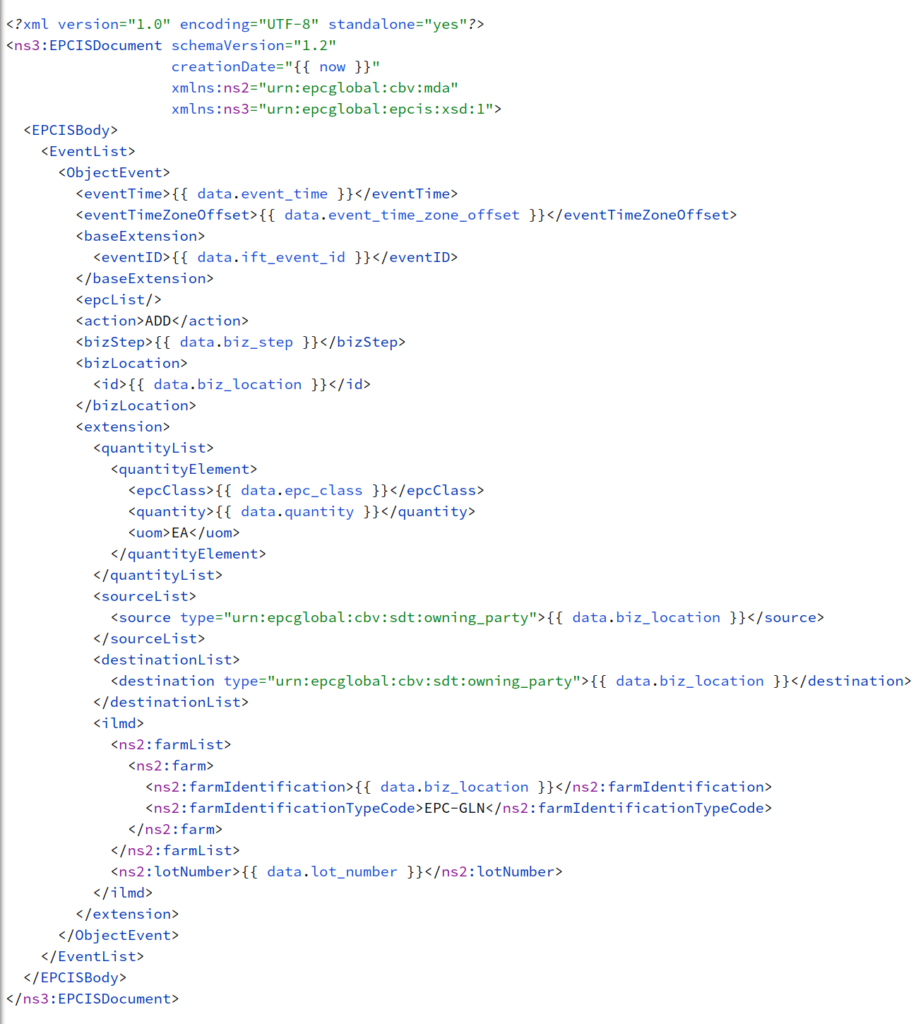
XML Gen
It turns out that the events we create in the production management system can be translated into similar events in IFT. The data we store in this way in IFT is based on GS1 EPCIS Standard 17. We have created an XML template for each type of event which is filled in with data for the current event and then uploaded to IFT. In addition to this information, we register every combination of seeds and suppliers we use as ”products” in IFT, as well as a ”location”, our aquaponics farm. These templates are based on GS1 GDSN Standard 18 and data in IFT is created in a similar way from a combination of XML templates and data from the production management system. IBM has a wiki on GitHub with information about how they use these standards, about the APIs of IFT etc that we have benefited a lot from.
IFT defines a number of different events and we have used three types to register our data; Commission, Observation and Transformation. These three events are defined in EPCIS. The Commission event is used when a new unit of a particular product is to be registered. We use this event to register the production management system Plant event. Observation is used to register a change in an existing unit. We use this type of event to register the events Seedling and Harvesting from the production management system. Finally, we use a Transformation to record our Plant events. It transforms one product into another. In our case, we transform a seedling into a plant. This models well the practical transfer of the seedlings from the cultivation tray to the rafts where they grow into finished plants.
Data display
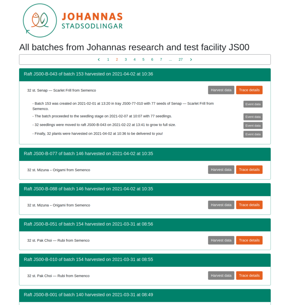
Data display retrieves data from IFT via several API calls (endpoints). With the help of the call “/ products” we get a list of all registered products. Based on this list, we can then retrieve details about each harvest. Then we retrieve complete product data for each harvest so that we can show what type of plant and supplier it consists of. Finally, we use the call “/ trace” to get the “history” for each harvest, ie the four events in the plant’s life. In this way we can show the full history of each harvested plant.
Discussion
This prototype is very minimalistic, but it still includes the fundamental parts of a blockchain-based tracking system. We could deliver our products with a label in the form of a bar or QR code, which would link to a website where the buyer can get the full history of how the plant came to be.
[track’n’trace image?]
At present, there is no information about what happened to the product from the time it was harvested until the customer has it in their hands, but if you also trace this part, the chain could be extended and the entire process could be documented on the blockchain in IFT. That part of the tracking could be done by a delivery company and/or by the store that sells the product. The various parties would store “their share” of the information separately in the blockchain at the same time as the customer can see the entire resulting sequence of events.
In the future we could also include more information like the environmental ”footprint” of the product and its nutritional value. This would of course require more thorough data gathering and analysis on our end than we are capable of at present, but it is definitely something we are discussing.
This concludes our series Build an aquaponic indoor farm. At least for now!
The text in this posted is licensed under Creative Commons BY-NC-SA International.