This is a description of how we at Johannas Stadsodlingar (urban farms) and Concinnity together have built Johanna’s aquaponic pilot facility. We want to share how we did it and our thinking behind it. There is quite a lot to think about, so there will be several posts to cover most things.
Part 1 – to start, prior knowledge
Part 2 – design (this post)
Part 3 – building log
Part 4 – water quality and nutrients testing
Part 5 – Production management
Our pilot facility consists of 290 m2 in an insulated building that was previously a cow barn for about 140 cows. The farm was built in the mid 80’s and was then very modern. We have taken a third of the space available in the farm building. The pilot plant uses three rooms: the large cultivation room, of approximately 220 m2, the seeding/sappling room 24 m2 and the ”packaging room” 20m2. The rest are side surfaces.
In the pilot plant, we will grow leafy greens, spices and rainbow trout (yes, nitrification bacteria of course).
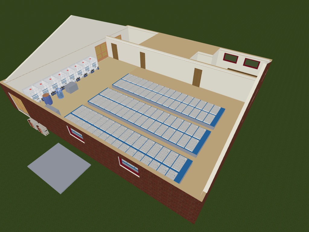
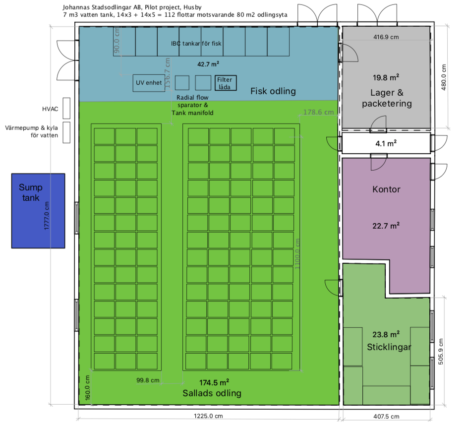
The first design was based around IBC tanks and three cultivation troughs with 60 x 120 cm rafts. Outside the building there is an area reserved for the sump tank. The fish would be in IBC tanks. We thought of using a radial flow separator to remove the coarsest solid particles and a filter box for the finer particles. Just as described in The Aquaponic Farmer (see part 1).


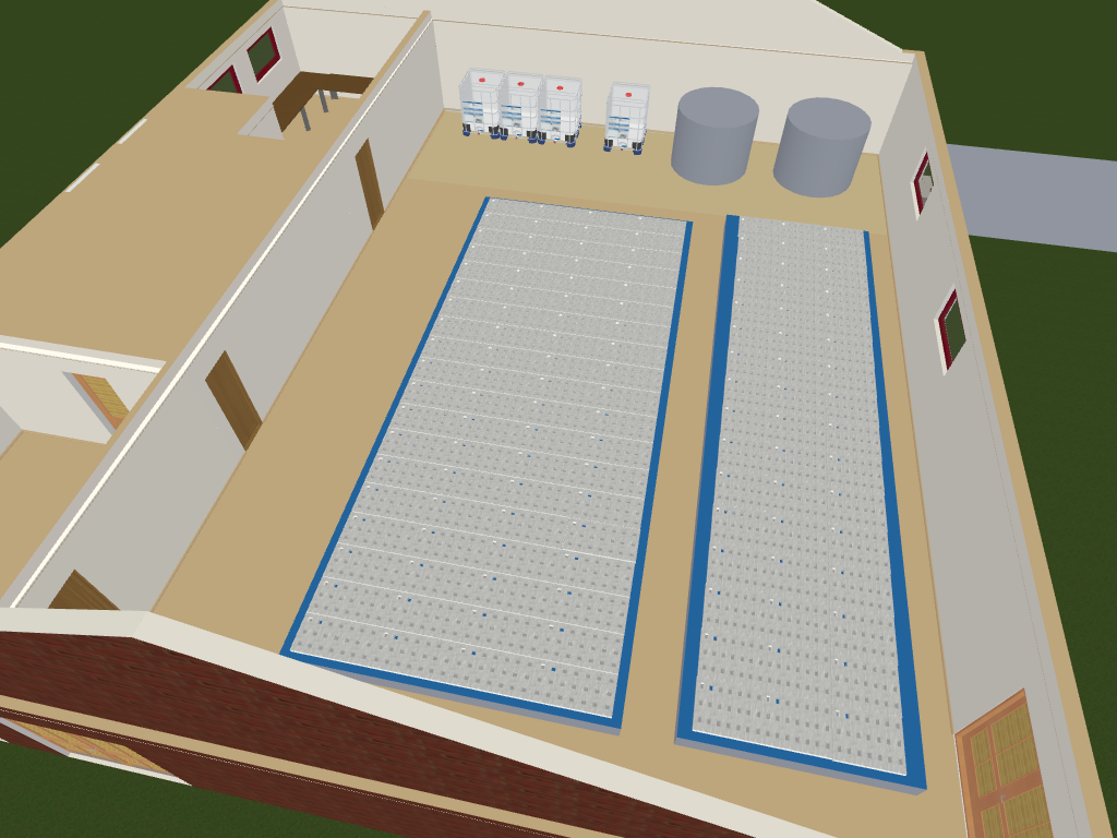
In the floor plan above, you can see that we have already rethought using two cultivation troughs instead of three. A narrower trough for rafts from Meteor Systems and one with more traditional rafts from Royal Brinkman (120 x 60 cm). In the Meteor rafts, we use a smaller substrate plug with significantly less material consumption. In the Brinkman rafts we use plastic pots. We were not sure what would work best in the Swedish market, so we wanted to try both.
Since we have a concrete floor, we can not have part of the filter system below the throughs easily, so we investigated other options for the filters. We chose to have a small drum filter instead. At the same time, we began to wonder if the fish we had decided on, the rainbow, would not feel much better in round tanks. In addition, we realized that the sump tank would need proper protection, so we started planning a building over the tank. Eventually, that building became our engine room as well. It turned out that this was very good, but it was a lot of work.
To have better access to the room where we ship out vegetables, we turned the design so that the fish tanks are furthest from the packing room, while it also has less people moving around the fish tanks (the doors are not there) which reduces stress for the fish. The round fish tanks are also more volume efficient.

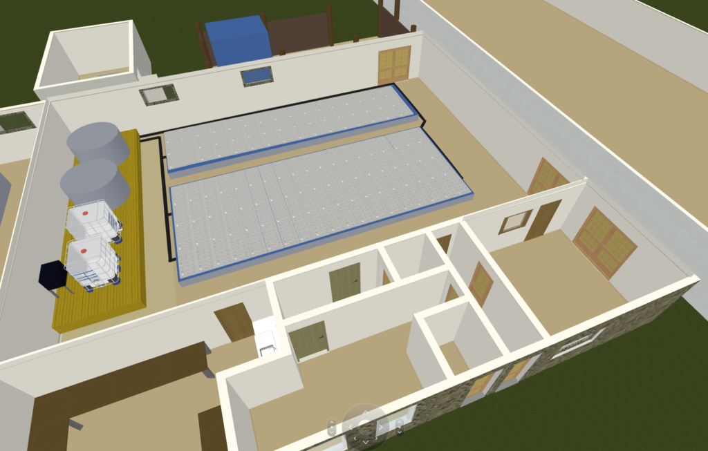
In the final design (below) you can see that we added a ”pier” around the fish tanks. The tanks were so high that it would be better to be able to get up a little when working there, without having to stand on a footstool. At the same time, we wanted to get the filter tank (Moving Bed Bio Reactor, MBBR) up from the floor, as the water level in our design is determined by the outlet on the filter tank as well as avoid pipes on the floor so you do not have to step over them all the time. Despite a lot of thinking around this, some of it came out less than optimal. We have a higher water level than we think is good and it would be quite a lot of work to rebuild it to lower the level. But, as I said, the goal of a pilot plant is to learn.

The facility has 3782 growing places in the two troughs, approximately 3200 growing places (depending on which trays you use) in the tables in the sampling room. We can have a total of about 7000 plants in the system at the same time.
The water tanks are 9.5 m3 each. We have an IBC tank as MMBR (1m3). The sump tank holds approximately 4 m2, but we normally use 2 m2 of the space. The cultivation troughs together hold approximately 23-25 m3 (depending on how high the water level we set). Together, the total system uses approximately 35 m3 of water. We also have an IBC tank that will be used as a quarantine for incoming fish and preparation tank before slaughter.
On the far side of the building you can see the sump tank building (beyond the round fish tanks) and the blue cube is a three meter container that contains a diesel powered generator.
In the next blog post we will document our building process in a build logg.
The text in these posts are licensed under Creative Commons BY-NC-SA International.
