This is a description of how we at Johannas Stadsodlingar (urban farms) and Concinnity together have built Johanna’s aquaponic pilot facility. We want to share how we did it and our thinking behind it. There is quite a lot to think about, so there will be several posts to cover most things.
There are quite a few parts to the work of building a pilot plant for aquaponics. When we started, we thought it might take 9 months to do the job. We were wrong. It took almost two years. We worked mostly in the evenings and weekends during the first 9 months. After that, one of us started working full time in the company and during the past year we have also had additional help full time. We did not spend all the time building, but a large part of the time was spent on construction.
- Part 1 – start and prior knowledge
- Part 2 – design
- Part 3 – build log (this blog)
- Part 4 – water quality and nutrients testing
- Part 5 – Production management
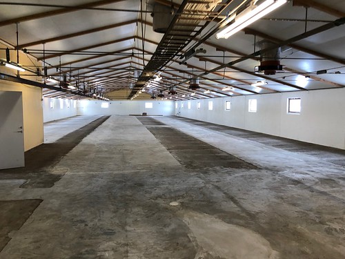
The building we are in a is an old farmhouse for cows, built in the eighties. It is 900 squremeters, and about 55 meters long and 16 meter wide internally.
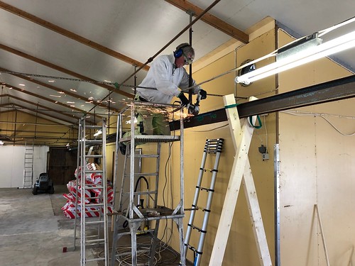
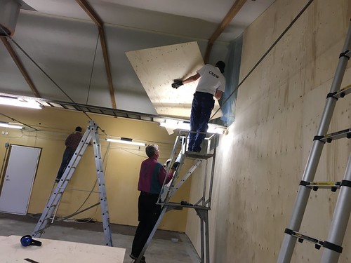
First we had to remove old equipment, such as the milk tank and the traverse for the feed wagon. Below, it is Micke who cuts the I-beam for the traverse where we would build the wall.

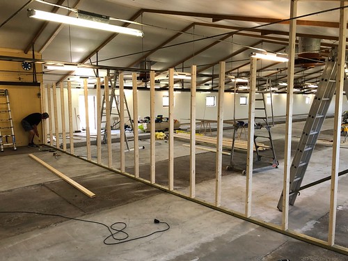
We chose not to use the entire building for the pilot plant, so needed to build a dividing wall. Here we see when Thomas, Micke and William are working on it.
The building had not been used (other than temporarily as a warehouse) for almost 15 years, see we needed to clean everything: walls, roof, cable ladders. It was a lot of work. Here Anke Johanna cleans the ceiling.

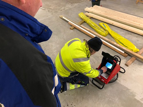
We needed to inspect the drains to make sure they did not have any serious leaks. The drains are used to carry faeces from the fish to an external manure tank. Here Rasmus helps us to inspect the pipes.
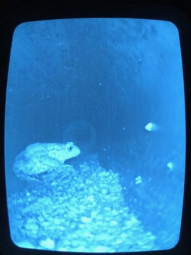
In the drain we found a toad that seem to live there during the winter.
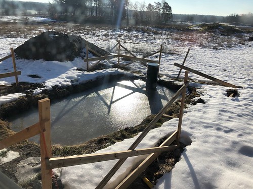
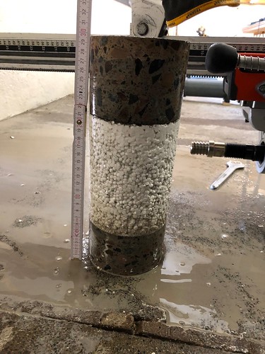
We had decided to have an external sump tank. We needed to know that it could be dug at the location we chose and that it would not reach the bedrock, so we enlisted the help of a neighbor who dug a test hole with an excavator. The ”test hole” became large enough that we could improve it a bit by hand (William digs and Micke measures where to put the building) to later use as a hole for the sump tank. The hole was not really straight, as you can clearly see later.
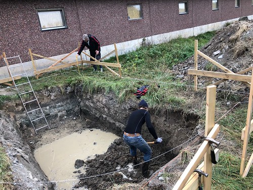
Work went a little slow so before we could work more on the sump tank and the building on top of it, the winter arrived and the hole was filled with groundwater and froze.
 We built a sump tank structure in wood, which Mikael was happy with, that we later dressed in a rubber lining.

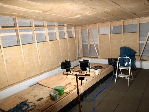
The room that previously had the stall for the calves needed to be furnished to have a table for sowing and the small plants. We call it the cutting room or the calf room. First we needed a floor so we could install new drains.

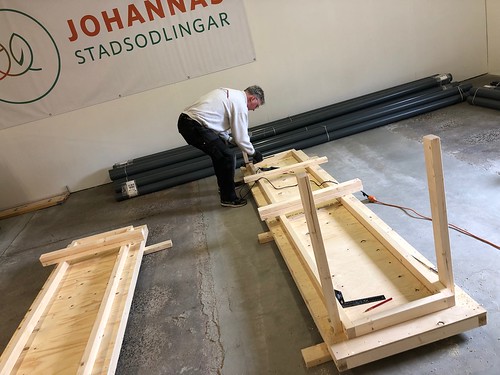
Here Mikael builds a table for the small plants, that will stand in water in trays.
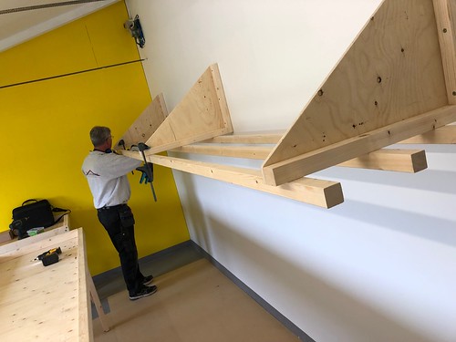
We thought for quite some time about how to hang the LED lights. In the end, it was a fairly simple construction in wood that actually works really well. Mikael came up with a good design in the end.

The tables being covered by rubber lining.
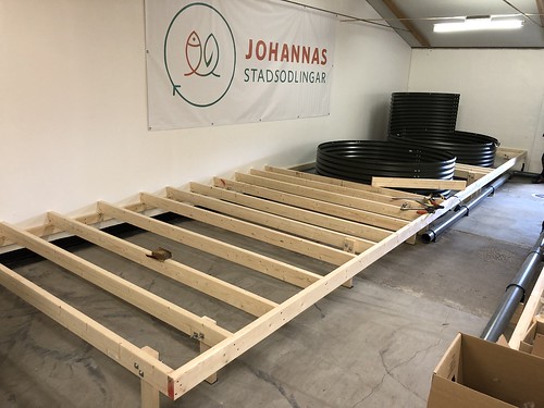
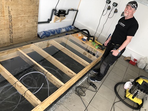
Building the large troughs for the plants was quite a lot of work, as the floor tilts quite a lot. We have a 10 cm difference between the highest and lowest point on the troughs at a distance of five to six meters. Each piece must be sawn perfectly and measured in place with a laser.

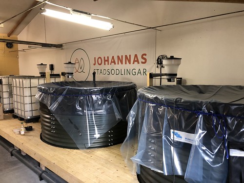
We bought rainwater tanks with custom fitted rubber lining as fish tanks. Two tanks that hold approximately 9.5 cubic meters. We do not recommend that choice, but more on that later. Here Mikael cuts a hole for the outlet.


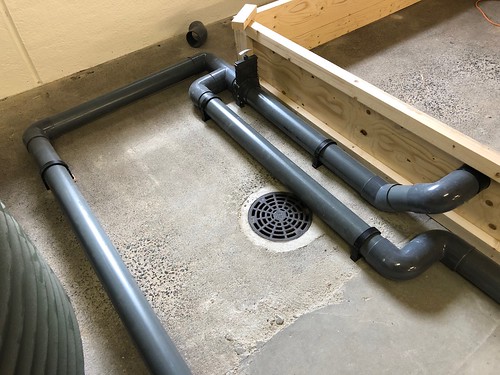
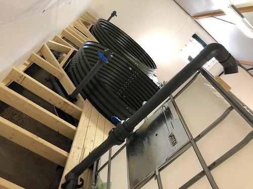
Piping with 110 mm PVC-U pipes from the fish tanks to the cultivation troughs. There you can also see the evacuation well that we created at the lowest point in the event of a flood. It turned out to be good to have in the future on several occasions.
In parallel with this work, work was also underway to build our sensor system. Here, Stellan shows the first sensor hub, which measures slightly different things in the cutting room: light, temperature, humidity, carbon dioxide. We later added a sensor to the electricity meter. It also acts as a hub in the alarm system and has, among other things, an SMS modem.

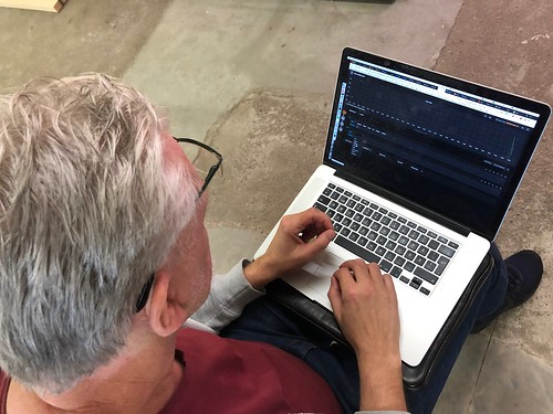
Here Gabriel is inspecting the first data packets that arrive to our data visualisation system which is based on Grafana and Graphite.
Now we needed to connect the water system inside the building, fish tanks and cultivation troughs to the outside where the sump tank will be located. Mikael drills holes in the wall.

Here you can see that our building is well insulated. We have about 15 cm of cellular plastic between the inner and outer wall.
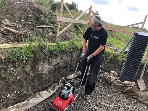
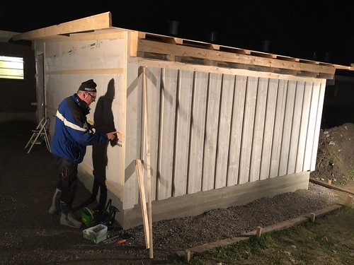
Then we started constructing the building where the sump tank is located. We needed to cast pillars on which the foundation will rest. It was really shitty weather when Mikael and William made the holes for them with a drill.

We prepare a stable and insulated base for the sump tank.
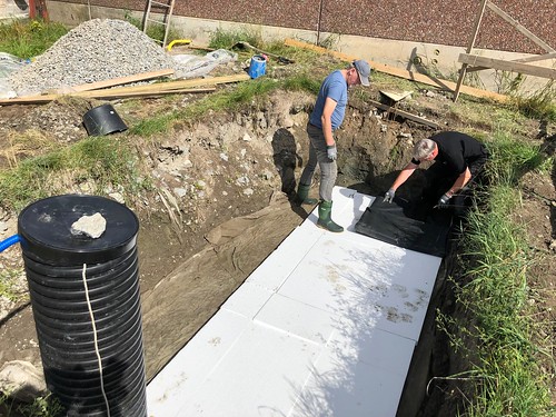
Then we lay the rubber lining that should be on the outside of the sump tank. (It’s made of wood, so it needs to be protected.) We got good help here from Stellan and Gabriel.
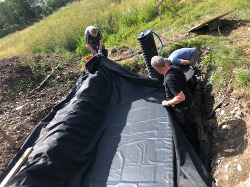
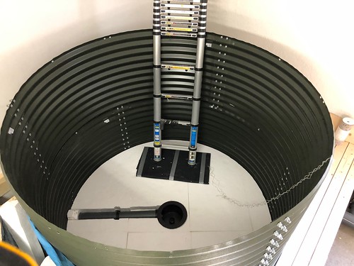
The sump tank is put in place and then we put on the internal rubber lining.


The sump tank gets insulation. We also cover it up so that it doesn’t fill with rain until the roof gets built.
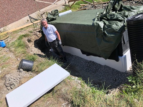
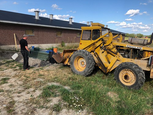
Filling with gravel and soil around the sump tank. William drives his large back loader from Volvo, which we are very happy to have had access to.

A timelapse of pouring the concrete for the foundation of the sump house. The whole gang came out that day and helped.

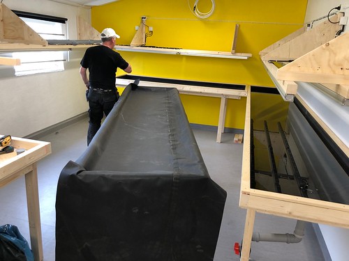
Then we started to build the platform, or pier as we call it, around the fish tanks, on which the filter tank will also stand. We see William adding floor boards.

The concrete floor that we have in the building is more or less in direct contact with the ground below, so we wanted to insulate the cultivation troughs. In addition, the rubber cloth becomes less sensitive if you have to walk on it if there is not a hard surface underneath. Here we have a timelapse of installing insulation, the rubber mat and the air hoses in one of the troughs.

We have installed air stones in the troughs to make sure that we do not get stagnant water and enough oxygen for both the bacterial culture and the plants’ roots. It is possible that we went a bit overboard with the amount of stones.

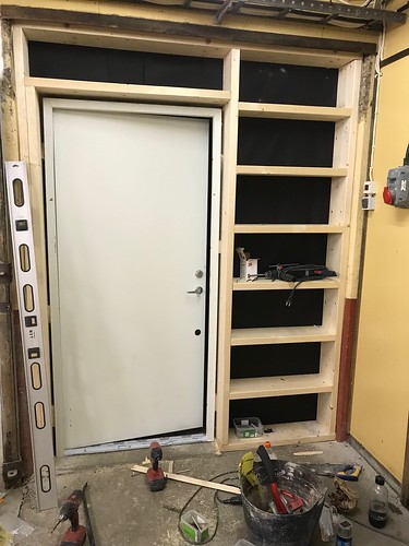
We also had to replace all the doors, which we got second hand.
We insulated the fish tanks at the bottom, so that they came at the right height for the outlets and pipes. After the rubber lining was installed in the tanks, we covered them to avoid getting building dust in them.
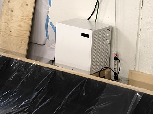
To reduce the humidity in the main growing room, we chose to install a dehumidifier. It will be more expensive in the long run than installing proper ventilation, but for now we can make do with a dehumidifier.
The it was time to build the sump tank building. That turned into many a late night.

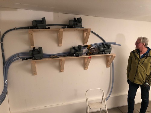
Installation of the air pumps. It was good that we had a well-insulated sump tank building to install them in. They make a lot of noise.

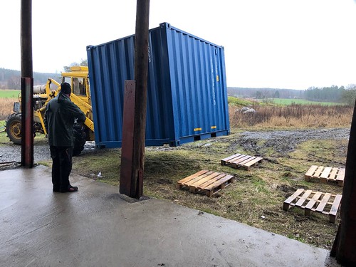
The electricity network where our facility is located is not good. So a backup generator is necessary. But, since we work with live animals, we must have reserve power anyway. Here comes an insulated container for the backup generator.
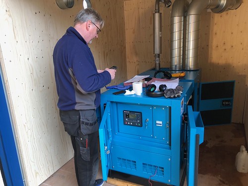
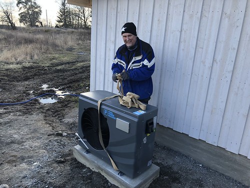
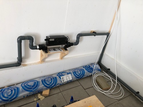
To maintain the right temperature in the water, we have an air-to-water heat pump. For emergencies, there is also an electric heating cartridge installed, which the reserve generator is able to handle the load from.
When the weather got better, we were able to finish the roof of the sump tank building (Tomas working on it) and paint it (Anke).


We also installed a plexiglass lid on the sump tank so it is easy to see that the air pumps work and that the water level is where we expect it to be.
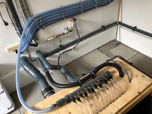
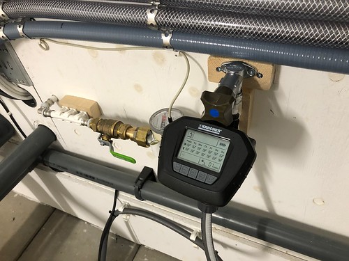
Detail of water piping, air hoses, water meter, electric wiring etc.
When we started filling the system with water, it turned out that we did not do the right thing when we glued the pipes. Many of the pipes needed additional gluing before we got rid of all the leaks. It took several weeks of work. Tip: When gluing PVC-U pipes, have plenty of glue on both pipes. Rubber lining bushings must have suitable glue properly applied.

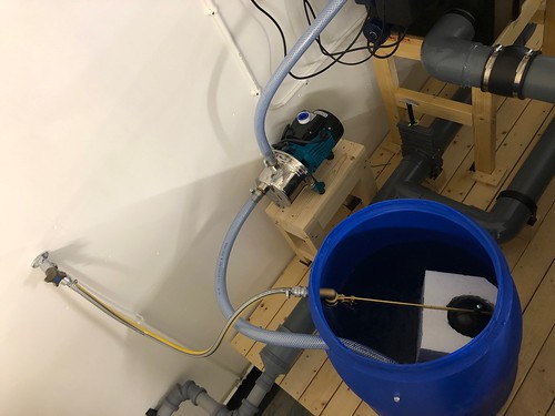
Our first attempt to feed the pump for the drum filter used a 120 litre barrel and automatic filling with well water. We had problems with the drum filter flushing at the wrong time or for too long. For that the barrel did not hold enough water. We redesigned this completely. At first we switched to taking water from an IBC tank, but in the end we did what we were supposed to do from the beginning: take water from the clean side of the drum filter.
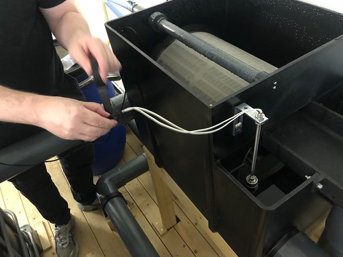
We had to install a max water level sensor on the drum filter to regulate the flushing pump.
When we were satisfied that the leaks were fixed and that the filter flushing worked well, Lisa added bacterial media to the bacteria tank (Moving Bed Bio Reactor – MBBR).


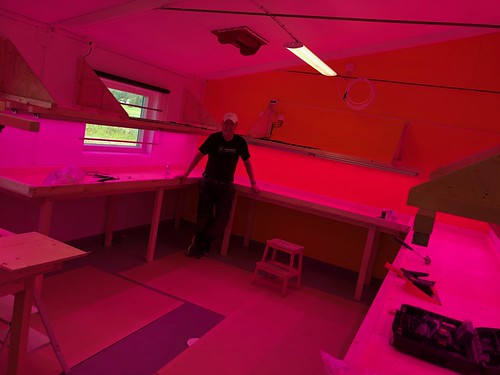
We fed the bacterial culture with a little ground up fish food, but mainly with food grade ammonium chloride in powder form. The ammonia was added to a bucket of water the day before it was to be used and then bubbled with an aquarium pump for 24 hours to get rid of some of the chlorine. When the nutrient levels started to rise (ammonium converted to nitrite and nitrite to nitrate) we started to grow plants in the troughs.

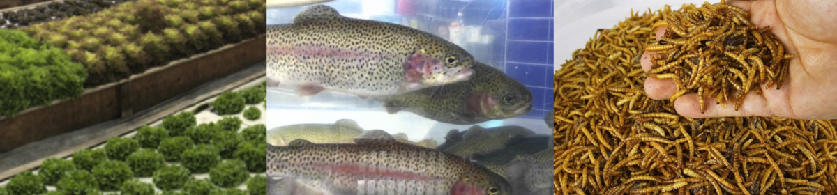
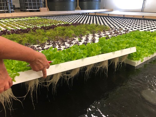
Even without fish in the system and very low nutrient levels, we saw surprisingly good growth, which was even better when the fish arrived.
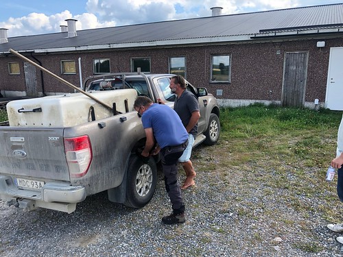
But eventually the fish came to our system. Here Tomas talks to Peter who delivers our smolt. We use rainbow in our system from 50 grams to 1.2 kg.
The sensor system measures a number of different parameters every minute. Here you can see some.
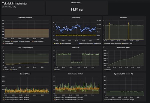
The sensor system delivers data locally to a small computer, but also to our cloud service, so that we can access the data on our mobile phones around the clock, without opening the internal system to the outside.

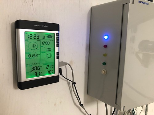
The sensor box in the sump tank house also talks to a weather station that sits on the roof. (Even when it is zero degrees outside, we have 30 C in the sump tank house, it may have been a little too well insulated …, the heat comes from the air pumps.)
Inductive water sensor on the outlet pipes to the fish tanks. It is one of the systems that can send alarms directly to our mobile phones if the water stops flowing in the pipes.

Automatic water filling for the sump tank. We take system water to rinse the drum filter. That water goes to the manure tank. The fish feces and that water eventually becomes manure for the fields around the farm. Now water recovery in our system is about 99.5%, which we think we can improve to 99.9% or better when we start processing the fish feces for reuse in the system (remineralising it) instead of making manure for the fields.
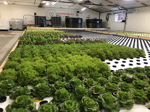
A picture of the system in production. We have faster and better growth of our plants than we expected!
In the next post, we will discuss a our sensor and data system.
The text in this posted is licensed under Creative Commons BY-NC-SA International.